Relay attached to furnace blower motor common wire. During this leading event of the asian hvacr world huayi had the opportunity to present its latest innovations in compressors for the commercial and domestic refrigeration markets focusing on energy efficiency and r290.
Adding driving lights that come on with the.

You can find out more Diagram below
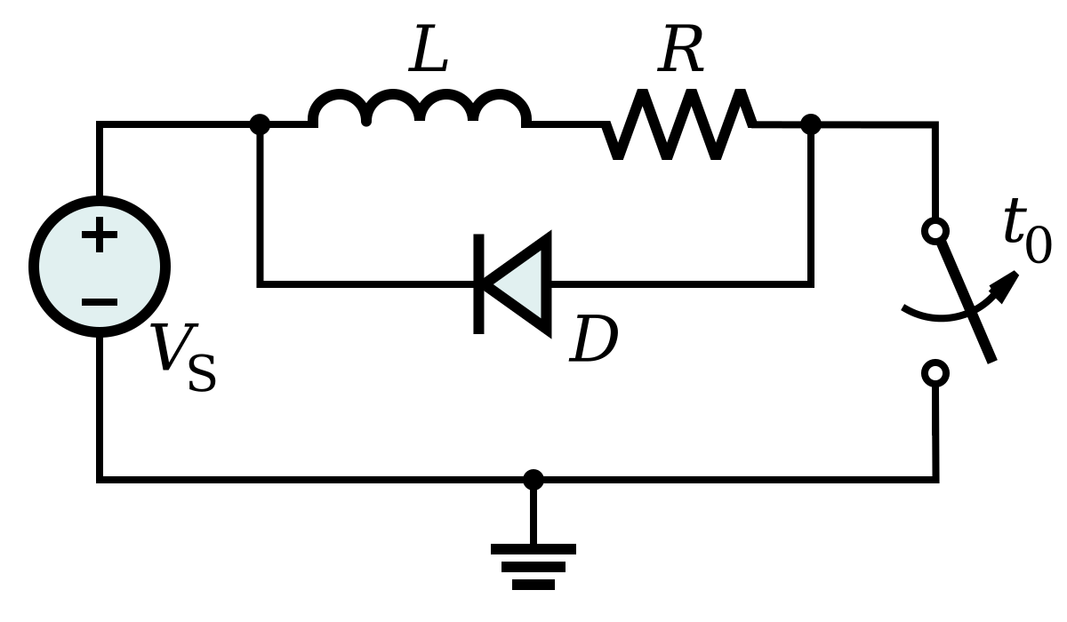
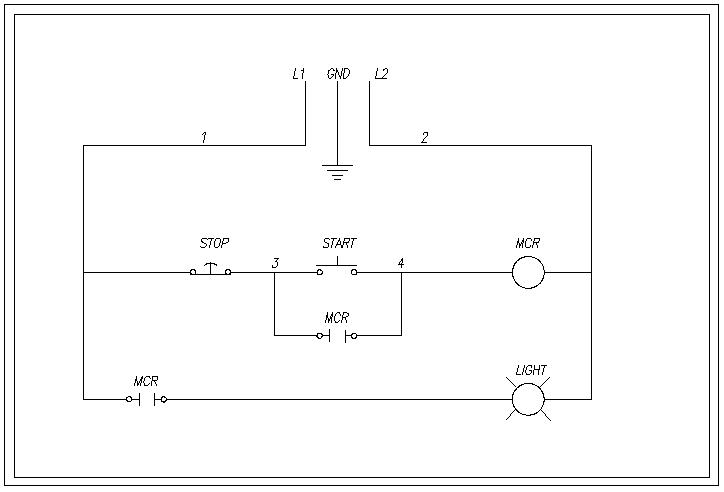
Current relay wiring diagram. Example relay wiring schemes. As in the diagram a wire is run from a 12 volt power source to the switch in the cab and out to the relay placing a fuse at the source of the power. The following diagrams show some common relay wiring schemes that use 4 pin iso mini relays.
Service maintenance hvac residential market air. Presented using advanced software cg animation technology to help you understand. The role of starter relay is to control the high current with low current protect the ignition switch and reduce the line drop of the starter solenoid switch.
The single relay controlled starter solenoid wiring diagram is as shown in the following picture. See how theyre triggered and how current flows though them. High current capacity wiring and switches cost more than lower current capacity versions so by using relays the requirement for the more expensive components is minimised.
Figure 2 rsir motor diagram push on current relay. The square relay pinout shows how the relay socket is configured for wiring. Home know your potential starting relays.
This pinout image is only a 2 pole diagram for room on the page purposes but you can get the picture here with this one since a 3 pole will just have 1 more set of contacts. Part of our wiring diagram and electronic series. If the current draw is less than 40a loop the com mon wire at least twice or more times around the bracket ensuring that the common wire passes between the bracket and the relay housing.
Remember when a start capacitor is being used terminals 2 and 3 may come into play. Humidifier wiring the relay is wired in series with the humidistat. Huayi group participated at china refrigeration exhibition held this year in the shanghai new intl expo centre from april 9th to 11th.
Terminals 4 and 6 are sometimes referred to as dummy terminals and are simply used for wire connections. This is usually the higher of the two terminals on the relay. The back emf voltage generated across the start winding causes a small current to flow in the start winding and potential relay coil.
Minals is required see figure 3. The neutral wire must be attached to the relay so that it is in series with the relay coil. If a two terminal relay is used without a start capacitor then figure 1 current relay cut away.
Also when wiring capacitors to a motor using a current relay always wire the starting capacitor in series with the start winding. This should help technicians wire a current relay to a compressors motor. Follow the relays wiring schematic when connecting the wires to the relay one of the relays terminals goes to ground.


0 comments:
Post a Comment