Understanding the basic light switch for home electrical wiring. Need a light switch wiring diagram.
Wiring diagram for electric motor with capacitor best single phase.

You can find out more Diagram below
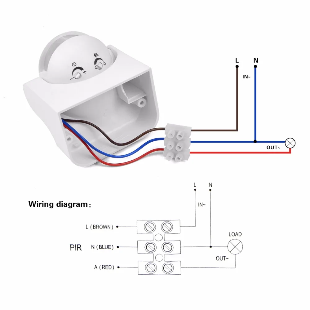
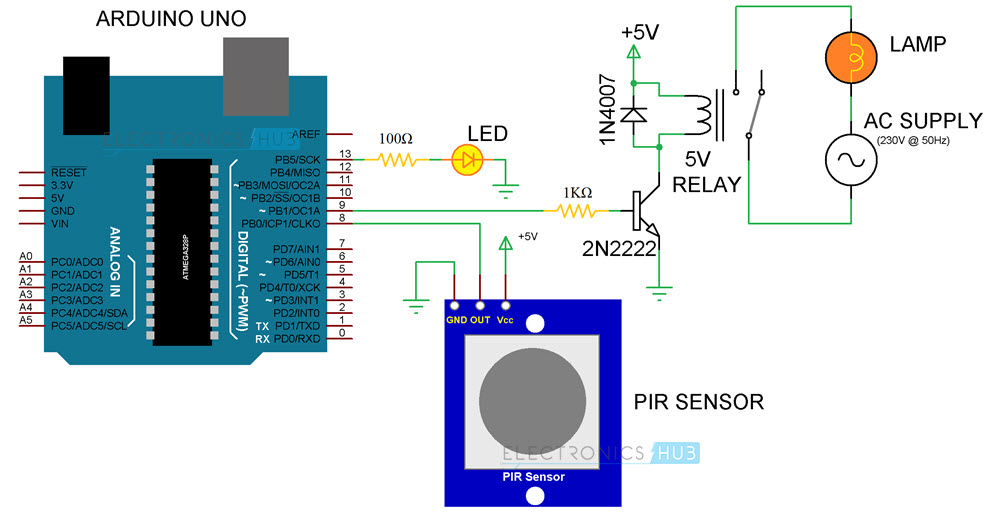
110v light sensor wiring diagram. And best of all wiring the fixture isnt that difficult to do. Pir sensor module ckt l how to work sensor in hindi duration. Wiring 220v to 110v here you are at our site this is images about wiring 220v to 110v posted by alice ferreira in wiring category on oct 20 2019.
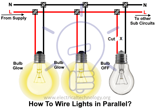
This diagram illustrates wiring for one switch to control 2 or more lights. Multiple light wiring diagram. The source is at sw1 and 2 wire cable runs from there to the fixtures.
Three wire sensors are used in various applications from detecting parts to locating position of the actual machine. They can come in all different technologies such as inductive photoelectric and capacitive just to list a few. Whether you have power coming in through the switch or from the lights these switch wiring diagrams will show you the light.
Wireless motion sensor lights a wireless sensor works like the remote control for a garage door opener. Although the sensor technology may differ all 3 wire sensors are wired the samea three wire sensor has 3 wires present. This light switch wiring diagram page will help you to master one of the most basic do it yourself projects around your house.
Electric motor wiring diagram 220 to 110 image. Easy to understand light switch wiring fully explained light switch wiring with diagrams and pictures with step by step instructions to guide you. Electric motor wiring diagram 220 to 110 download.
There are some limitations to this system. The hot and neutral terminals on each fixture are spliced with a pigtail to the circuit wires which then continue on to the next light. Just screw the receiver into a light socket and mount the sensor anywhere you like.
More electrical tips and diagrams wwwaboutelectricitycouk. No wiring is necessary to control existing lights. You can also find other images like images wiring diagram images parts diagram images replacement parts images electrical diagram images repair manuals images engine diagram images engine scheme diagram images wiring harness diagram images.
Electric motor wiring diagram 110 to 220 collections of phase meter wiring diagram wires likewise convert 220 to 110 volts. In this video you will see how to wire pir sensor light in the ukit will also show you internal wiring of pir sensor and light. How to wire a light switch diagram 1.
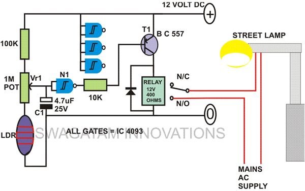
By installing an outside post lamp that has a built in light sensor youll never have to worry about those concerns ever again. With a light sensor controlling the function of the light it automatically turns on when the sun goes down and turns off when it comes back up. It sends a radio signal to a receiver that switches on a light.


0 comments:
Post a Comment